First, the twisted nematic phase (TN) display
TN type liquid crystal display device is the most common liquid crystal display device. Commonly used watches, digital meters, electronic clocks, and liquid crystal display devices used in most calculators are TN type devices. Generally, as long as the liquid crystal display device used for the pen-type digital display is mostly a TN type device. Therefore, this device should be the most well-known liquid crystal display.
The basic structural principle of the TN type liquid crystal display device is: lithography of a transparent transparent electric plate pattern of the glass having the ITO transparent conductive layer, and clamping the front and rear two glass substrates with the transparent conductive electrode pattern to the upper layer A nematic liquid crystal material having positive dielectric anisotropy is sealed around to form a flat liquid crystal cell having a thickness of only several micrometers. Since the inner surface of the glass is coated with an oriented layer film and subjected to orientation treatment, liquid crystal molecules are arranged in parallel along the glass surface in the cell. However, since the orientation directions of the orientation layers of the two inner surfaces of the glass are perpendicular to each other, the liquid crystal molecules are twisted by 90° between the two glasses, which is the origin of the twisted nematic liquid crystal display device. 1 is a configuration of a TN type liquid crystal display device, and FIG. 2 is a schematic diagram thereof.
Figure 1 Schematic diagram of a typical TN liquid crystal display device
(a) Schematic diagram of molecular arrangement and transmission of light for TN devices
(b) Schematic diagram of the TN type electro-optical effect
Since the twisting pitch of the liquid crystal molecules in the TN type liquid crystal display is much larger than the visible light wavelength, when linearly polarized light having a uniform or orthogonal alignment of liquid crystal molecules along one side of the glass surface is incident, The polarizing direction is twisted by 90° after passing through the entire liquid crystal layer, and is emitted from the other side. Therefore, the liquid crystal cell has a light shielding between the parallel polarizing plates, and the surface can be shielded between the orthogonal polarizing plates, and between the orthogonal polarizing plates. The function and function of light transmission.
If a voltage is applied to the liquid crystal cell at this time and reaches a certain value, the long axis of the liquid crystal molecule will start to tilt in the direction of the electric field. When the voltage reaches about 2 times the threshold voltage, all the liquid crystal molecules except the surface of the electrode are in the liquid crystal cell. The liquid crystal molecules between the electrodes become rearranged along the direction of the electric field. At this time, the function of 90° optical rotation disappears, and the optical rotation is lost between the orthogonal polarizers. Make the device not transparent. Since the surface loses the optical rotation between the parallel polarizers, the device can no longer be shielded from light.
Therefore, if we place the liquid crystal cell between the orthogonal or parallel polarizing plates, the light can be changed by the power supply to the liquid crystal cell to change its transmission-covering state. Usually, we see the black words that appear in the liquid crystal display device, not the liquid crystal is discolored, but the liquid crystal display device transmits or absorbs light.
Second, super twisted nematic phase (STN) display
As the name suggests, "super-twisting" means that the twist angle should be large, more than 90 °, which is a dot matrix liquid crystal display device which is currently used more. We know that the electro-optical response curves of TN type and most other types of liquid crystal display devices are not steep enough.
As the driving voltage increases, the electro-optic response increases slowly, and the threshold characteristics are not obvious. This causes difficulties for multi-channel driving, which makes the liquid crystal display limited in large information display and video display.
In the early 1980s, it was found that conventional twisted nematic liquid crystal (TN) devices can improve their driving characteristics by increasing the twist angle of their liquid crystal molecules. After efforts, people have successively developed a series of liquid crystal display devices that exceed the TN twist angle by 90°. We call such liquid crystal display devices with twist angles of 180° to 360° called the super twist (STN) series.
At present, almost all dot patterns and most dot matrix liquid crystal display devices have adopted the STN mode. STN technology is in a mature and perfect stage in the liquid crystal industry. The product structure of the STN mode is basically the same as the TN mode, except that the arrangement of the liquid crystal molecules in the box is not arranged along the 90° twist, but is twisted by 180° to 360°.
LCD schematic
LCD driver
First, static drive
The basic idea is to apply an electric field continuously or no external electric field between the corresponding pair of electrodes.
As shown in Figure 1:
Driving circuit principle: as shown in Figure 2:
Drive waveform:
According to this electrical signal, the pen segment waveform is not in phase with the common waveform or is inverted. When there is no electric field on the liquid crystal in the same phase, the LCD is in the non-strobe state. When inverted, a rectangular wave is applied to the liquid crystal. When the voltage of the rectangular wave is much higher than the liquid crystal threshold, the LCD is in the strobing state.
Figure 3. Static waveform
Second, multi-channel drive
Basic ideas:
The electrodes are arranged in a matrix in the X and Y directions (as shown in Fig. 4), and a gate waveform is applied to the X electrodes in order, and a gated or non-strobed waveform synchronized with the X electrodes is applied to the Y electrodes, so as to repeat. Through this operation, the phase of the intersection of the X and Y electrodes can be independent or non-selected.
Figure 4. Electrode array
The time required to drive the X electrode from the first line to the last line is the frame period Tf (the frequency is the frame rate), and the ratio of the time Tr used to drive each line to the frame period is the duty ratio: Duty=Tr/Tf=1/N.
Voltage averaging:
It can be seen from the basic idea of multi-channel driving that not only the voltage is applied to the strobe phase, but also the voltage is applied to the non-gating phase. The ratio of the waveform voltage at the time of non-strobe to the waveform voltage at the gate is the bias ratio Bias=1/a. In order to make the display state between the gated phase and the non-gated phase, the selected voltage Von must be consistent, and the non-selected voltage Voff is consistent. In order for the phase element to be gated under the gate voltage; and not gated under the action of the non-gating voltage, the photoelectric performance of the LCD must be required to have a threshold characteristic, and the steeper the better. However, due to material and mode limitations, the steepness of the LCD electro-optic curve is always limited. Therefore, it is required that Von and Voff are pulled more and better, that is, the larger the Von/Voff is, the better. According to theoretical calculations, when Duty and Bias satisfy the following relationship, Von/Voff takes a maximum value. A that satisfies the following equation is the optimum bias value for the number of driving paths N.
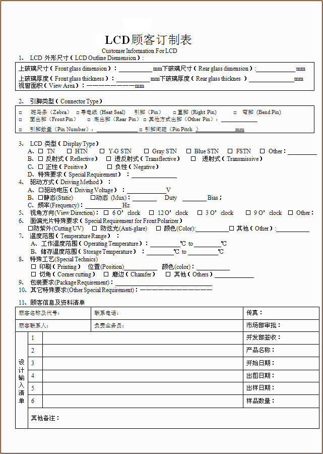
We can design and manufacture LCD screens with various sizes and different display modes according to customer requirements.
Production process:
1. Customer product design requirements include: appearance size (LCD size), window size, drive parameters (display content, voltage, temperature) and other requirements.
2. According to the customer's requirements, the company submits the design plan and drawings.
3. The customer confirms the drawing and confirms it.
4. Open the mold and sample.
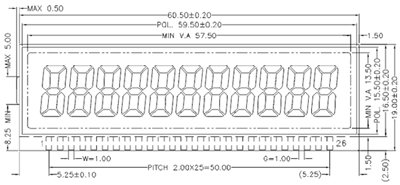
Design legend
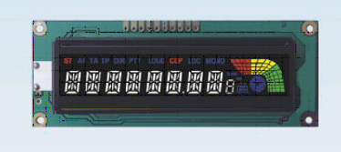
Product example
Shenzhen E Generation & Green Tech Ltd
© 2018-2020 Shenzhen E Generation & Green Tech Ltd All Rights Reserved. 粤ICP备17164667号 Powered by: ytclouds.net
 1037872034 Mr. Long (Sales)